
LOOKING FOR SOMETHING?

Tag: Aerial Equipment

Using Technology to Eliminate Aerial Device Overloads

Knowing bucket capacity and understanding how to read a jib load chart are two critical elements of aerial device operation. While both tasks are fairly straightforward, it is crucial to stay within the allowable capacity of the unit. The platform capacity and material-handling capacity provided by the manufacturer are not recommendations – they are absolute maximum capacities that ensure the machine is not overloaded. Overloading equipment can result in overturning or boom failure. Equipment damage also may occur, resulting in costly repairs and a shortened usable life for the aerial device.

A fully equipped lineworker with PPE plus tools and materials for typical line maintenance can quickly add up to 700 pounds or more for distribution work, and upward of 1,000 pounds for transmission work. Bucket capacity is identified on the ID plate and inside of the basket on most aerial devices. In addition, be aware of dual-rated buckets with different capacities based on configuration and use as a material handler; these types of buckets are available from some manufacturers. Before climbing in, lineworkers should verify that their weight – in addition to the platform liner, if used, and all of their tools and equipment – doesn’t exceed the bucket’s capacity.

“Don’t forget to account for boots, harness, tools and any components you may add to the bucket once you are elevated,” said Kyle Wiesner, aerial products engineering manager for Terex Utilities. “Tools such as phase lifters, crimpers, hydraulic drills or chain saws all add up. Weight of personal clothing can change with the weather, so don’t forget to recalculate come winter. If a component is in the bucket while work is being performed, that weight needs to be factored in as well.”

If it is not equipped with a material-handling feature from the manufacturer, the aerial device must not be used to lift material with the platform or boom. The platform is not intended to handle material – only tools and equipment the operator can carry that fall within the platform capacity.

Further, if gear is not labeled with its weight, lineworkers shouldn’t guess. Instead, use a small, portable scale to verify total weight before loading the bucket. Once you have weighed a tool or piece of gear that you use often, mark it with a small tag or permanent marker so you will have a record of the weight for next time.

Proper Jib Use
Proper jib use requires an understanding of how to read a load chart, plus knowing the upper boom angle, jib angle and load radius as specified on the load chart. Maximum permissible load on the jib varies depending on the boom and jib configuration. It’s necessary to verify the setup before a load is lifted.

While different bucket, boom or power-line positions dictate at what angle the jib is able to be used, the upper boom angle must be verified by looking at the angle indicator located on the boom. In addition, some jibs extend, which will increase the radius of the load, thereby decreasing capacity. A trial run with the boom and jib positioned as needed will provide the information necessary to confirm jib capacity. “It’s a good idea to keep a measuring tape handy to verify load radius,” Wiesner said.

The next step is to confirm that the weight of the object to be lifted is less than the maximum jib load for any configuration, from picking the load to placing the load. Load charts typically are located on the dash plate or boom tip, visible to the operator.

If it’s determined that the current equipment would overload the bucket or jib for the task to be performed, figure out what rated capacity would better meet the application. Then, if possible, use several machines – such as a digger derrick with the aerial – to aid in accomplishing the task, or purchase or rent the proper equipment. In any case, always encourage proper operator behavior and treatment of the equipment in order to keep employees safe.  

Technology Can Help Change Behavior
While understanding these principles is basic for journeymen, what if there was an operator aid that could assist lineworkers with these tasks? Crane manufacturers and some non-insulated aerial manufacturers have applied sophisticated load-moment indicators to computer monitoring systems for years, which provide feedback to operators regarding load weight and capacities. More recently, self-propelled aerial lifts have been designed with active working range monitors of platform movement. Currently, new standards – EN280 for Europe and ANSI A92.20 for some equipment in the U.S. – require aerial work platforms to monitor the weight in the platform and disable functionality if the load being detected is above platform capacity.

Dynamometers have been and continue to be available to aid equipment operators by giving them the ability to measure, not estimate, the load being lifted. The display on the dynamometer attached to the hook gives the load’s weight. Recently, load-measuring devices have been developed that work on insulated aerial devices in proximity to electrical fields created by power lines. The battery-operated radio devices provide a display near the operator that shows the weight of the load on the load line.

And rather than reinvent the wheel, Terex Utilities has collaborated with customers to create an operator aid that helps to inform lineworkers of a potential overload situation. The Terex Load Alert system consists of wireless sensors that measure boom angle, jib angle, jib extension length, jib load and bucket load. Visual and audible warnings at the upper controls indicate to the operator if the equipment approaches 90 percent of the maximum allowable capacity. By providing real-time feedback, including maximum allowable and actual capacities of bucket and jib, lineworkers can take corrective measures to prevent overload situations.

Unexpected Outcomes
For companies that have implemented the Load Alert system, several unexpected outcomes have occurred. Initially there was pushback from operators who felt like Big Brother was watching them. But now that trucks with the system are in the field, lineworkers have been surprised to find they were unintentionally overloading the basket or jib and could take immediate corrective action. The system also aids during training, and operators can be more accurate in setup, estimated weights, angles and other factors.

In addition, as data is monitored, it can be output through any telematics system. Utilities can track historical occurrences of overload situations and use the information to perform required inspection and maintenance as necessary. It also can guide training needs and aid in determining what is needed for future equipment purchases. When an overload occurs, an alert can be sent to a designated person via text or email, capturing the exact aerial configuration at the time of the overload. This information can be used in overload event investigations to recreate the work scenario and determine a training exercise that is anything but hypothetical.

System information also aids utility fleets in making more effective purchases by providing fleet managers data about, for example, how often a jib is used or the average weights of loads lifted or how much basket capacity typically is used. This can result in savings by reducing equipment purchase costs, or it might support a fleet manager’s proposal to buy an aerial device with higher capacities for applications that warrant it.

Ultimately, it’s all about the numbers. Operators are responsible for calculating loads in the bucket and on the jib and verifying them against available capacity. New technologies can aid in those processes, increasing accuracy, but they cannot replace the operator’s knowledge – and following – of safe work practices.

About the Author: Dan Brenden is director of engineering at Terex Utilities (www.terex.com/utilities). He has more than 17 years of experience as a product manager for Terex.

3 Tips for Site-Conscious Aerial Device Setup

Aerial devices are among the most important pieces of equipment in a utility company’s fleet. They are another tool in the utility’s toolbox and – like any other tool – must be properly used and maintained.

While it’s the responsibility of the employer to ensure that each individual operator is correctly trained and qualified to operate an aerial device, it takes the whole crew to contribute to safe and efficient operations. Following are three important steps crews should take before work starts on any project that requires use of an aerial device, plus real-world tips from Garry Christopherson, director of safety and security for Dairyland Power Cooperative in La Crosse, Wis.

Step 1: Conduct a site survey.

  • Identify potential hazards, such as buildings, ditches, drop-offs, holes, debris, sewers, overhead obstructions, electrical conductors and underground utilities.
  • Evaluate the ground conditions. The ground must be firm enough to bear the pressure produced by the bucket truck – including the maximum platform and jib loads – during operation. You may need to use pads under the outriggers to distribute the weight over a greater surface area. If your bucket truck does not have outriggers, or if it is equipped with only one set, make sure all the tires and axle suspension springs are equally loaded. If the ground is slippery, snowy or icy, consider how to prevent the vehicle from sliding.
  • Consider the terrain. If the vehicle must be parked on a slope, keep the boom on the uphill side, chock the wheels and work off the rear of the truck. Per ANSI A92.2, bucket trucks are stability-tested on firm, flat surfaces up to a 5-degree slope. Never work on a slope greater than what is allowed by the manufacturer. Use your bucket truck’s chassis level indicator to make sure the truck is always set within the manufacturer’s operational limits. Most aerial truck manufacturers, including Terex, equip their vehicles with an inclinometer that is used to determine if the truck is set up within the allowable limits. Follow the instructions for your vehicle, and recognize that some trucks must be leveled before raising the booms.

Co-op Tip

“We send right-of-way agents and surveyors out to the project site prior to job startup to determine if we need any special permits from the DNR or wildlife organizations to work in the area,” Christopherson said. “We then work with these groups to ensure our site setup is safe for our crew and equipment, as well as for the environment.

“Depending on the ground conditions, we may use special matting to park our trucks on, or create a road or special access point for our trucks to travel on,” he continued. “In addition, we put up fencing or other barricades to make sure we protect site conditions.”

Step 2: Conduct a visual inspection.

  • Follow the aerial device manufacturer’s inspection and maintenance requirements.
  • Perform a visual walk-around inspection of the entire aerial device for things like structural issues, as well as damaged, loose or missing fasteners, pins or covers.
  • Verify that ground and platform controls are operating properly.
  • Check oil, fuel, tires, suspension, torsion bars, outriggers and safety equipment for any leaks, loose items, cracks or damage before work begins.
  • Using the lower controls, raise and lower the booms through a complete cycle, looking for any malfunctions or problems.
  • Repair damaged items before use. Always contact the manufacturer if there is any question whether something needs to be repaired.

Co-op Tip

“When multiple operators use the same truck, no one operator can assume that he or she knows exactly the condition the truck was left in by the previous user, which further emphasizes the need for preflight visual inspection and cycling,” Christopherson said. For more information about daily preflight inspection requirements, refer to section 8.2.3 of the ANSI A92.2 standard.

Step 3: Hold a job site briefing with the crew.

  • Review conditions of the job site and potential hazards. Traffic exposure is one of the greatest challenges. Line personnel must take traffic control efforts seriously, including positioning signs – and using flagmen if needed – before and after the work area to capture the attention of drivers sharing the road.
  • Review necessary tools and equipment. Aerial devices are designed to lift personnel. Do not use them to lift or lower objects unless the aerial device is specifically designed and equipped to do so. Know the maximum bucket and material lift (if applicable) load capacity, and do not exceed it at any point during operation. That means you need to know how much each person, tool and accessory weighs before getting into the bucket. Anticipate how much weight from job site materials (e.g., wood chips that accumulate during work) could be added during operation. Operators must wear an OSHA-compliant fall arrest system with a lanyard attached to the aerial device anchorage at all times. Crews also must be equipped with other PPE, including insulated hard hats, hearing and eye protection, proper boots and suitable clothing. Consider the potential for arc flash exposure and provide additional PPE as required.

Co-op Tip

“Dairyland Power conducts four-day training sessions that include both classroom and hands-on learning,” Christopherson said. “We also work with equipment manufacturers, like Terex, to develop strong training programs based on the operator’s manuals and practical applications. Operators need to be able to assess the situation and make decisions based on what is going on.

“Once our site survey is done, the crew leader holds a job briefing to discuss all of the elements of the project,” he added. “These meetings are held every day we’re on-site, and every crew member must attend. It is important that each and every team member understands what needs to be accomplished and what challenges are involved. Because working around traffic is one of our biggest challenges, we follow established protocol for traffic control, setting up road cones or barricades and signs to divert traffic away from the work area. It is the crew’s responsibility to know and implement proper setup procedures once the site conditions have been assessed.”

About the Author: Jim Olson is product and safety engineer for Terex Utilities (www.terex.com/utilities).

*****

Important Reminders for Aerial Device Operators

  • Read, understand and follow the instructions in the operator’s manual and other manuals supplied with the vehicle.
  • Never operate the aerial device without knowing the location, function and operation of all the controls, including emergency and accessory operation.
  • All ground personnel must be trained in the proper procedures to follow in case of an emergency.
  • When operating the boom, always operate controls slowly and deliberately for smooth movement. Avoid abrupt starts, stops and reversals of direction. Rough handling may cause damage to the aerial device and endanger the operator.
  • Always be aware of your boom’s trajectory before you begin operating. Do not place the boom in open traffic lanes. Stop traffic or barricade lanes to divert traffic from the area.
  • Always level the unit to within the manufacturer’s limits before raising the bucket. Once the bucket is raised, do not adjust outriggers.
  • Operators must always stand with both feet on the bucket’s floor. Do not sit on or climb onto the edge, or use planks, ladders or other devices for a work position.
  • Protect your crew from falling objects and debris. Keep all ground personnel away from the area directly under the work point unless absolutely necessary, and caution them that it is necessary to constantly be on the lookout for possible falling items.
  • Always maintain proper clearance from energized power lines. Your bucket truck cannot protect you from phase-to-phase or phase-to-ground contact, which means you need to allow for sag, sway or rocking as you are positioning and operating your aerial device.
  • Do not allow any ground personnel or bystanders to touch the aerial device, the vehicle or an attached trailer while the aerial device is in operation near electric power lines, even if the aerial device has an insulated lower boom.
  • If any part of the boom touches an energized object, it should be considered energized.
    If any part of the boom contacts a grounded object, it should be considered grounded.
  • Be aware of any obstacles the lower boom may strike if rotated or elevated, as well as any objects that the booms may come close to as movements are made.
  • Do not override any safety devices.

Important Considerations When Spec’ing Lift Controls

The lift control panel on an aerial device is an important element for effectively running the unit, enabling the working platform to be propelled into a desired location. Similar to how a steering wheel gives a truck-mounted aerial device mobility to get to and from a job site, the lift control panel gives the machine’s operators the ability to quickly and easily position the platform into the work area.

But because the operator control station is relatively small, it’s not always top of mind when new units are being spec’d. Given the importance of lift controls on aerial devices, however, following are some insights to consider when spec’ing them.

The foundation of every control panel is the ability for operators to use it to control the aerial device’s vertical longitudinal (or extend-and-retract) and rotational (or side-to-side) movements. For instance, most aerial device control stations are equipped with a single joystick. The joystick is designed to give operators control of the machine’s boom functions from one handle. “A common industry standard on an aerial device’s lift control panel is a three-function joystick,” said Dan Brenden, director of engineering for Terex Utilities (www.terex.com/utilities). “This type of joystick allows operators to move the individual booms up and down, as well as to rotate the unit.”

Four-function single joysticks are available as an option. This type of joystick enables operators to extend and retract the boom on articulating models, or it can operate elevator sections, if equipped, giving users even more control and functionality from one joystick. According to Brenden, “Terex uses similar single joystick designs across its entire aerial device product line, keeping uniformity within the brand, so from the smallest to largest machines, all controls function the same for the operator.”

Control stations may also include the ability to control platform/basket movements. This feature elevates the platform, regardless of the boom’s position, allowing operators to gain several feet of working height to access hard-to-reach work areas. The operator’s ability to control the speed of the functions can also be located on the control station. Brenden mentioned that Terex offers a two-speed control option.

Air-operated chassis engine stop and start plungers are an option at the platform, allowing operators to quickly and easily turn the chassis engine on or off. Control stations are also equipped with an enable lever, which provides operators protection against inadvertent operation. According to Brenden, the enable lever must be actuated, in combination with the lift control movement, before any platform movement is allowed.

The type and arrangement of an aerial device’s lift control panels can vary from platform to platform, and from manufacturer to manufacturer. Additional functionality and control options on a lift control panel will depend on the machine’s specific options. “For example, if the machine has a basic jib, the lift controls will include functions for winch and jib articulation,” Brenden said. “If the machine is equipped with a hydraulic extend jib, that adds the need for more controls. The more options an aerial device has, the more controls needed.”

About the Author: Amber Reed is a consultant for Signature Style PR + Marketing, based in Huntersville, N.C.

*****

Safety Features on Lift Controls
An aerial device’s lift functions are controlled by the operator, either in the platform or at the control station at the base of the unit, said Dan Brenden, director of engineering for Terex Utilities. All aerial devices are fitted with controls in both locations.

Safety is of utmost importance when operating an aerial device. Every device is outfitted with a lower control station at the base of the machine that overrides the platform controls. This offers several benefits, including the ability to lower the lift if an operator, working at height, becomes unable to operate the controls. There is also a control option that allows the operator and unit to be safely lowered in the event of an equipment power failure.

Nonmetallic control handles are another standard safety feature on a control panel. The single joystick is dielectrically tested and may provide limited secondary protection between the metallic components of the boom tip and handle. “It is important to note that this handle is not rated for electrical protection, although it may provide limited secondary protection from incidental contact,” Brenden said. “It is not intended to replace safe work practices or primary protection, such as maintaining distance, cover-up and personal protection equipment.”

Evaluating Medium-Duty Powertrain Options for Aerial Trucks

Aerial lift trucks are built for low-mileage, high-engine-hour duty cycles, with unique payload requirements. So what should you consider in terms of the powertrain – the engine, transmission and drive axle options – to spec the best chassis for the job? Utility Fleet Professional spoke with Ryan Kloos, chassis technical coordinator for aerial platform manufacturer Terex Corp., to get his advice.

We centered the conversation around an example of a Class 7 chassis, rated up to 33,000 pounds gross vehicle weight (GVW), that might be used for a 50-foot aerial application. This is because smaller trucks typically have only a few engines, transmissions and drive axles to choose from. But when you move up to a Class 7 or heavier chassis, the specification process gets much more complex, with some models offering more than a dozen different powertrain configurations that can significantly impact the truck’s highway speed, fuel economy, performance and price.

UFP: When evaluating diesel engine horsepower and torque ratings, how do you sort through the myriad options to determine the best fit?

Kloos: The big thing is the work environment of that truck. Is it off-road? Will it operate in a mountainous area? Then there are payload and trailering requirements. You want to make sure the truck has enough power to move the weight and pull the trailer, while achieving sufficient top-end speed.

UFP: How does this translate into an actual engine spec?

Kloos: Take the 33,000-pound GVW truck example. If it’s a typical 4×2 application, a smaller 250-horsepower and 660-lb-ft torque [diesel] engine seems to cover most requirements. But when you get into applications where you may be pulling a little bit heavier trailer behind that truck or get into extreme off-road applications or a mountainous area, we’ll look at increasing horsepower and torque from there.

There’s also the cost factor. The higher up you go in engine horsepower, the higher the cost. So, we’re trying to offer as much truck as possible for as little cost as possible. And a 250-horsepower engine in a 33,000-pound GVW truck seems to hit that sweet spot in a wide range of utility applications.

UFP: What about selecting the transmission?

Kloos: The manual transmissions are obviously a lot lower cost and have their advantages as far as [low-gear] performance, but for the most part, the Allison automatic [3000 RDS series] brings a lot of simplicity in terms of driving the truck – and it’s the drivability of the automatic that operators really enjoy.

UFP: Drive-axle gear ratios often seem like an afterthought, but the wrong spec could significantly impact top speed, fuel economy and the ability to handle off-road and steep grade conditions. What should utility fleet managers consider?

Kloos: The big factor when you start talking about gearing is the top speed requirement. In a lot of cases, utility fleets are looking for off-road performance, but they also want to be able to get the truck to run at highway speeds. So it’s a matter of finding that happy medium in there between the transmission gearing and rear-end gearing. We need to configure the spec to meet the max speed, fuel economy and performance requirements.

When you consider a 33,000-pound GVW truck in a 4×2 application, you want it to handle 75 mph highway speed, while still offering good low-end startability. In this case, we typically recommend about a 6.17:1 rear gear ratio with a 250-horsepower engine and six-speed automatic transmission. If you’re pulling a trailer, you would adjust the gear ratio accordingly.

We often receive requests where the customer will say, “Our old truck we’re replacing has a 300-horsepower engine and it’s just not enough power for what we need it to do. So we want our new truck to have 350 horsepower.” But we usually try to explain that the reason the 300-horsepower truck didn’t perform right is because it was geared for a 95 mph top speed. If you don’t need that truck to do 95 mph, we can bring that down a little bit, lower your top gear speed and give you a little bit better performance without you having to spend all the money for a bigger engine.

*****

Rear-Axle Ratio Spec Guidelines
In medium-duty trucks, gear ratios can range from 2.69:1 to 7.17:1, depending on the truck class, make and model, and rear-axle capacity. How do you determine what’s right for your application? The following general guidelines should help point you in the right direction:

• For maximum towing and payloads, and on hilly terrain with steep grades, ratios at or nearing 7.17:1 should be considered depending upon severity.
• When the truck requires flexibility for operating on varied terrain with moderate towing and payloads, ratios in between the extremes should be considered. One can bias toward either end of the spectrum based upon the frequency of off-road events.
• For flat terrain, lighter loads and running at consistent highway speeds, a ratio closer to 2.69:1 should be selected.

19 Exciting Utility Fleet Products and Services for 2015

Product: Ultra Pad Safety Edge
Company: Bigfoot Construction Equipment
Web: www.outriggerpads.com

Bigfoot Construction Equipment offers the all-new Ultra Pad Safety Edge, which helps to prevent the outrigger from slipping off the outrigger pad. Call 888-743-7320 for more information.


JJ Kane 1

Product: Auction Services
Company: J.J. Kane Auctioneers
Web: www.jjkane.com/construction-utility-equipment-cars-trucks

J.J. Kane Auctioneers is a nationwide auction company that conducts 40-plus absolute public auction sales each year. They make it easy, connecting sellers and buyers both face to face on-site and live online, with Internet bidding. Sellers include electric cooperatives, utilities, manufacturers, contractors, lending institutions, governments, rental companies and more. J.J. Kane specializes in utility, power-line, underground and construction equipment, and fleet vehicles. In addition to physical auction sales, the company offers its Live Off-Site service, enabling sellers to participate with equipment from remote locations. Live Off-Site allows sellers to be a part of the excitement created by a live physical auction sale, when transportation costs or logistics are a factor. J.J. Kane can provide a turnkey solution, handling every aspect of the sale process.


Al Asher

Product: TSE Cable Scrapper
Company: Al Asher and Sons Inc.
Web: www.alasher.com

The TSE Cable Scrapper is Al Asher and Sons’ latest product innovation for 2015. Formerly known as OK Champion, the industry has long recognized the Cable Scrapper as the go-to product for salvaging underground cable up to 4-inch diameter. The machine will pull, cut and load cable all day long in one continuous operation, saving countless man-hours and extra equipment. Now you can purchase the TSE Cable Scrapper with remote radio controls for the bed winch, which will digitally and effortlessly record pulling torque and speed. Enhanced hydraulic circuitry improvements also are available to promote longevity and reduce heat and wear in the system. Asher stocks units for sale or rental throughout the USA.


International Truck

Product: International WorkStar Truck
Company: Navistar/International Truck
Web: www.internationaltrucks.com
The International WorkStar is one of the most durable and versatile trucks in the utility industry, built on the same battle-tested truck platform as the International MaxxPro MRAP (Mine-Resistant Ambush-Protected) armored vehicle. It brings the strength and rugged capabilities to work power lines in any environment, with the smarts of Diamond Logic to operate efficiently and keep your team safe. Ease of Diamond Logic integration with utility equipment means that features such as boom operation alerts, remote engine controls and remote battery shutoffs are all factory-built options. The 2016 WorkStar is also offered with the industry-leading Cummins ISB6.7, a recognized platform that delivers renowned efficiency, reliability and performance.


Golight

Product: LED Stryker
Company: Golight Inc.
Web: www.golight.com

The new LED Stryker from Golight offers tremendous intensity and clarity with minimal strain on the vehicle’s electrical system. The LED upgrade boasts a 50 percent increase in intensity compared to its halogen counterpart. By utilizing P-Vex lens technology coupled with the cutting-edge LEDs, the LED Stryker is able to generate a peak beam intensity of 320,000 candela. Additionally, the hot spot – the most intense portion of the beam – comprises nearly 70 percent of the beam circumference, three times that of a comparable halogen unit.

The LED technology utilized in the new Stryker model generates nearly four times as many lumens per watt as a traditional halogen light source. Such efficiency means that the LED Stryker delivers more light while reducing the amp draw by half. Plus, the LEDs are incredibly durable with a rated useful life of 50,000 hours.


MUD TRAKS

Product: Rigid Access Mat
Company: MUD-TRAKS
Web: www.mud-traks.com

MUD-TRAKS’ strongest, most rigid access mat – designed to move heavy vehicles over wetland-like ground conditions – is light enough for men to handle in the field. It is made from solid fiberglass with an internal grid structure that channels tire load over an area more than 15 times larger than a comparable-sized poly mat. It is rigid enough to bridge a 20-inch span while supporting 10,000 pounds of tire load.

This innovation comes in three distinctive model strengths: Lawn Mat for vehicles up to 35,000 pounds, Off-Road Super Lite Mat for vehicles up to 60,000 pounds and Off-Road Super Mat for vehicles that weigh 100,000-plus pounds.

The mat’s advantages include strength, longevity, ease of handling and safety. It has numerous applications in the utility and heavy construction industries; is not affected by chemicals, temperature or water; and does not conduct electricity.


ShermanReilly

Product: Revolution Series Stringing Equipment
Company: Sherman+Reilly
Web: www.sherman-reilly.com

Sherman+Reilly designed its Revolution Series equipment around operator safety, ergonomics and environmental comfort. With a 14,000-pound pulling capacity, the Revolution Series P-1400X Single Drum Puller is a transmission-class drum puller with a first-of-a-kind drum engagement system utilizing lateral sliding sides and drum support rollers for simplified pulling and reconductoring operations. The P-2000X Bullwheel Puller offers a new design that provides a smooth 20,000 pounds of control for the steel hard line with the use of its twin hydraulically driven bullwheels. Both machines utilize automatic horizontal levelwinds that permit overhead rope retrieval with precision control.

The Safe-Zone Cab is an important feature of these pullers. The cab employs a floor-to-ceiling polycarbonate front window for maximum visibility while providing superior protection against impact.


Altec

Product: AT40GW Aerial Device
Company: Altec
Web: www.altec.com/products/aerials/telescopic-articulating/at40gw

Altec’s AT40GW track-driven aerial device has a 43-foot working height and 30-foot side reach to provide versatility in small or congested job sites. The telescopic/articulating boom design offers access to the platform from the ground. A 34-inch retractable track allows the device to easily maneuver in and out of gates and other narrow passageways by reducing the width of the machine. The unit comes standard with a walk-behind remote control for easy operation. A 180-degree platform rotator provides more flexibility in confined spaces to give the operator the best possible vantage point. For convenient transport, the 1,000-pound cargo deck accommodates transformers, tools and other components.

The AT40GW is available with an ISO-Boom, which allows the unit’s second stage to be fully retracted while maintaining dielectric integrity and meeting OSHA guidelines for minimum approach distance. With a Category C isolating fiberglass boom, the operator can work safely regardless of the upper boom extension.


Polaris

Product: RANGER ETX
Company: Polaris
Web: www.polaris.com/en-us/commercial/fleet-sales

The new RANGER ETX is an on-demand four-wheel-drive vehicle featuring a 31-horsepower, electronic fuel-injected (EFI) ProStar engine with an internal counter-balance shaft for smooth, low-vibration power. The dual overhead camshafts and a four-valve cylinder head work with the advanced engine management system to precisely deliver the fuel charge for impressive power and instant, predictable throttle response, while the lightweight, efficient transmission captures every ounce of power to deliver it to the ground. Like all ProStar engines, the design reduces internal friction, which dramatically reduces noise and significantly increases efficiency. The addition of EFI on this entry-level model assures easy starting, improved run quality and elevation compensation to ensure reliability normally found on higher-priced models.


Versalift

Product: Aerial Lifts
Company: VERSALIFT/Time Manufacturing
Web: www.versalift.com

With more than 50 years of innovation, exceptional quality and hard work, VERSALIFT’s legacy of success has been marked by talented employees, notable clients and innovators. The company – a global leader in aerial lifts – continues to adapt to changing markets in an ever-changing world, with a clear commitment to quality though unequaled innovative design and manufacturing.

Time Manufacturing strives to build the safest, most efficient and hardest-working machines to get the job done. Its product line has grown to encompass models for every market. With more than 300,000 square feet under one roof, its manufacturing facilities comprise one of the premier factories of its kind in the world. Through vertical integration, Time monitors and maintains the quality of all products from the initial purchase of steel all the way through final testing. Whether it be a 29-foot man lift or a 108-foot material handler, there is a VERSALIFT to get the job done.


Bronto Skylift

Product: S 150 XDT Aerial Work Platform
Company: Bronto Skylift
Web: www.bronto.fi

Bronto Skylift’s S 150 XDT truck-mounted telescopic aerial work platform is especially well suited for the rental market. It’s a lighter-weight, compact aerial that is road-legal in all states, so it can be driven to almost any work site, quickly set up and elevated to overhead areas in a matter of minutes. Mounted on a CAT chassis, it features a 152-foot overhead working height and a telescopic, articulating platform boom that provides 100 feet of horizontal outreach for increased up-and-over capabilities. With 360 degrees of continuous turntable rotation and a 1,400-pound platform capacity, workers are able to carry tools and equipment to access almost any elevated work site.


Kenworth

Product: T370 Medium-Duty Conventional Model
Company: Kenworth
Web: www.kenworth.com

Kenworth Truck Co. is expanding its axle offering for its T370 medium-duty conventional model, adding 18,000-pound and 20,000-pound front axles this spring. The new offering will enable the truck to serve more construction, utility, fuel and tanker applications. The T370 is built to deliver exceptional value over the long haul, and these new options will expand an ever-growing vocational use of the truck.


Kiefer

Product: Hydraulic Beavertail
Company: Kiefer Manufacturing
Web: www.kiefermfg.com

Kiefer Manufacturing offers a heavy-duty steel, self-cleaning hydraulic beavertail on most of its industrial flatbed trailer line models. The hydraulic beavertail option takes away the need to lift heavy ramps. Fingertip operation of the hydraulic ramps is done through a key fob, or with a lever that is permanently mounted inside a conveniently located storage box.

The newly designed hydraulic beavertail has an 8,000-pound lifting capacity. The wiring system is housed inside a 10-mil polyester sleeve for durability and longevity.


ARI

Product: Garage Management System
Company: ARI
Web: www.arifleet.com/services/in-house_garage_maintenance/

ARI’s Garage Management System (GMS) provides fleets the ideal balance between in-house control and outsourcing convenience by helping to manage technicians, vehicle maintenance and parts inventory while simultaneously consolidating all vendor-in/vendor-out data. From mechanics’ hours to automatic routing of repair approvals and comprehensive repair history, GMS manages it all, and it can even feed data to integrated payroll or ERP systems.

The GMS module integrates all maintenance-related data in one place, allowing fleet managers to track, analyze and manage fleet activity to achieve the lowest possible total cost of ownership. By using GMS as part of a multifaceted maintenance program, fleets will experience cost savings through a more efficient repair process while also making it easy to increase patronage of external shops, balancing vendor mix.


Terex

Product: Cobra-Style Jib
Company: Terex
Web: www.terex.com

Available on all 24-inch-by-48-inch platforms, the Terex cobra-style jib is engineered with hydraulic articulation and extend, enabling operators to achieve a greater range of motion and increased productivity. It boasts a low, 16-inch profile, as well as a 600-pound platform capacity and 1,000-pound maximum lift capacity, which can be realized with the work line extended farther from the basket shaft than other jibs allow. Operators can easily rotate the cobra-style jib thanks to an additional bearing at the bottom of the jib. This rotation offers lineworkers more versatility at the pole, enabling them to easily line up with work as needed.

This jib also incorporates a poppet valve feature, which helps enhance safe work practices because it prevents the unit from damaging itself during operation.

The Terex cobra-style jib quickly retracts and conveniently stows out of the way. With the jib in the stowed position, the truck’s boom can still utilize its full range of motion, down to -40 degrees.


Hino

Product: Hino 338
Company: Hino Trucks
Web: www.hino.com/trucks/story_1212.php

Reliability is the key to success behind the Hino 338 model. This Class 7, 33,000-pound GVW model is equipped with the award-winning Hino J08 series engine rated at 260 horsepower and 660 pound-feet of torque. It also features a standard six-speed fully automatic 2500RDS with Shift Energy Management transmission from Allison Transmission, while 3000RDS and 3500RDS options are also available.

The Hino 338’s available 120,000-psi frame is strong and rigid enough for the high torque loads utility bodies demand. An available 14,000-pound front axle also adds to the durability that customers have come to know from Hino. All Hino Class 6 and 7 models offer a clean cab-to-axle, making the body upfit much easier and also allowing for more equipment in the rear of the vehicle.


GPS Insight

Product: GPS Dispatch and Custom Forms Applications
Company: GPS Insight
Web: www.gpsinsight.com

GPS Insight’s new capability to send optimized routes to drivers’ smart devices is the latest effort to simplify dispatching. You can now dispatch stops and/or routes via email or text message to each driver on a daily basis. For those customers who want to forgo Garmin integration, but need a better way to dispatch drivers, they can still do so. Also, drivers can now leverage directions used by the mapping apps on the smart device and do not need to be logged into another telematics app to be dispatched.

Garmin electronic custom forms were just added to the GPS Insight platform to improve the way businesses manage their mobile workforce from the field without all the paperwork. The forms are filled out on a Garmin and sent over the air to the back office for real-time data analysis. Utilities can use this function to expedite billing, improve productivity, track different types of completed services, perform job costing analysis and more.


PriorityStart

Product: PriorityStart HD
Company: BLI International
Web: www.prioritystart.com

PriorityStart HD is a totally automatic battery protection system that disconnects at 11.7 volts – stopping a dead battery – and then reconnects with a simple load change. The HD unit handles heavier loads, 60 percent increase to 1,600 starting amps and 400 continuous amps. The increase to the contact disc, gears and holding nut has strengthened the load capability and reduced the stress from heavier loads. Other improvements include increased points of connection, brighter top LED for easy viewing, motor/gear shielding strengthening operation and modified top post that easily accepts side-mount installation.


Mattracks

Product: YS3 and TA9000 Tracks Series
Company: Mattracks
Web: www.mattracks.com

Mattracks has introduced its new series of TA9000 tracks. The products expand Mattracks’ current Track-tor-Assist lineup of conversion systems for the agriculture market, commercial market, and extremely large machinery and equipment with axle loads from 10 to 20 tons. Track widths in the TA9000 series are 15 inches, 20 inches, 24 inches and 30 inches.

The YS3 track has been designed to expel snow and ice with minimal ice buildup, and the heavier framework has been designed for increased load-carrying capacity. The offset road wheels reduce vibration and noise, and increase efficiency, fuel economy and track tread life.

Shedding Weight of Utility Fleet Upfits to Boost Payload and Productivity

New diesel emissions aftertreatment devices – including diesel particulate filters, selective catalytic reduction systems and diesel exhaust fluid tanks – have added considerable weight to medium- and heavy-duty truck chassis in recent years. This has contributed to a payload challenge for many fleet managers, especially for those utility fleets operating Class 7 and 8 digger derrick and aerial platform trucks. They’re looking to keep their trucks within a certain weight range to comply with federal bridge laws and, if possible, avoid having to bump up to a larger chassis that may require a federal excise tax.

A federal excise tax applies to the first retail sale of a truck with a gross vehicle weight rating of 33,001 pounds and above, adding 12 percent of the purchase price to the total cost of a truck. So, having to go to a bigger chassis could mean as much as a five-figure increase to the cost of each truck. Spread that added expense across an entire fleet, and you get the idea of the financial stakes at hand with truck weight.

How can fleet managers reduce overall vehicle weight without having to upsize the truck? One solution is to shed weight from the body and equipment that are mounted on the chassis, replacing conventional steel – where feasible – with advanced lightweight materials such as aluminum, fiberglass composites, plastic composites and thinner-gauge steel.

Lightweight Potential
Conventional steel is the predominant material used in truck bodies because of its relatively low cost and the comfort level that many fleet managers have with its strength and durability to hold up under rugged working conditions. But steel is also heavy, and replacing it with lighter-weight materials could offer substantial weight savings and increased payload capacity.

According to Joe Caywood, senior marketing and product manager for Terex Utilities (www.terex.com), a global manufacturer of aerial work platforms, using fiberglass and aluminum can reduce the weight of a line body, also known as a utility body, by about 38 percent. So, what impact does that make in terms of real-world payload?

Take, for example, a standard steel 156-inch line body, which weighs about 2,300 pounds, Caywood said. Reducing the weight of that body by 38 percent translates into an increased payload capacity of 860 pounds.

Then there’s lightweighting the equipment mounted on the body. Caywood said that Terex has been able to generate 15 to 25 percent weight savings in their aerial platforms and other equipment by incorporating some high-strength steel – which is thinner and lighter than traditional steel, but with comparable strength – in the company’s upfit designs.

A side benefit of some lightweight materials, specifically aluminum, fiberglass and plastics, is corrosion resistance, which is important for the longevity of upfits. They must be able to withstand the corrosive impact of road salt in the Snowbelt states and salt air in coastal regions.

“Many fleets evaluate body material selection based on the region where the vehicle will operate,” said Justin Chandler, body sales manager for Altec Inc. (www.altec.com), a truck equipment manufacturer and service provider for the electrical utility and telecommunications market that offers fiberglass and aluminum bodies as part of its Green Fleet product line. “Some fleets may use more fiberglass in a region that is an intense corrosive environment, whereas steel – which is less expensive – may work fine in a less corrosive environment. The key is to find the best material solution for each customer based on the factors most important to them, whether it’s weight, cost or corrosion resistance.”

Balancing Act
Since lightweight materials tend to cost more than steel, too much of an advanced material could drive up the cost to a point where it’s not financially practical. And then there’s the issue of material strength, which impacts body durability and performance.

“Generally, you want to stick with steel for the understructure of the body, especially in utility applications, because of the potential twist and torque of the body, whether the truck is going off-road or carrying a crane or an aerial device,” said Eric Paul, regional sales manager for ETI (www.etiequipment.com), a manufacturer of aerial lifts, mobile service cranes and custom bodies.

Where are the most appropriate opportunities for lightweighting the body while keeping costs in line and without sacrificing structural strength?

“You want to look at nonstructural areas in the body – the side packs [the side compartments in line bodies], doors, floor pan – any area of the body that doesn’t absorb a tremendous amount of stress,” Paul said. “Fleets may wish to also consider composite bushings and aluminum or composite shelving.”

Said Caywood, “Look for opportunities, such as wire holders or different components of the body for storage that can be made out of aluminum or other lightweight material. Even something as simple as redesigning to reduce the inches of weld in the body design can reduce weight.”

“Lightweighting is a big balancing act,” Paul said. “And when it comes to selecting lightweight materials for a body, there is no one-size-fits-all solution. There needs to be an engineering mindset about it. Recognize the physical properties of each of the various materials and strategically include the right mix of materials for the body to do the job it has to do.”

Reducing weight of upfits will help increase payload capacity, but not all lightweight materials are created equal or suitable for every situation. Therefore, when considering lightweight upfits, work closely with your body manufacturer and upfitter to select materials that best fit the application – and your budget.

About the Author: Sean M. Lyden is a nationally recognized journalist and feature writer for a wide range of automotive and trucking trade publications, covering fleet management strategies, light- and medium-duty trucks, truck bodies and equipment, and green fuel technologies. He blogs at Strategy + Writing (www.seanmlyden.com).

Three Mistakes to Avoid When Spec’ing Aerial Platform Trucks

Considering that aerial platform trucks, also known as boom or bucket trucks, often carry a hefty six-figure price tag, it pays to confirm that the chassis, body and aerial equipment specifications fit the job before issuing the purchase order. The stakes are high because spec errors result in disruptive downtime, lost productivity and increased safety risks, taking a chunk out of a fleet’s bottom line.

And fixing the issue isn’t as easy as picking up a replacement truck at the local dealer because turnaround time on these trucks – from purchase order to delivery – can take anywhere from six months to a year and a half, depending on market conditions and chassis manufacturer lead times.

So, how can utility and telecom fleets ensure that they craft a spec that suits the application – to enhance productivity, worker safety and profit per truck? Steer clear of these three mistakes.

1. Assuming yesterday’s spec will work today
“The replacement cycle on aerial platform trucks is easily a decade, sometimes longer. So a lot can happen since you last bought a truck,” said Dave Blanding, order technical support, Terex Utilities (www.terexutilities.com), a global manufacturer of aerial work platforms.

One area of change that’s often overlooked is the impact of new diesel emissions technologies, such as diesel particulate filters and selective catalytic reduction systems, on chassis weight. “Trucks are getting heavier, not lighter,” Blanding said. “And the heavier the truck, the less you can put on the truck and stay legal. The fleet could be in the position of not having enough truck to carry all that they need to carry if they haven’t thought through the changes in the chassis and adjusted the requirements accordingly.”

Another factor to consider is any change in utility pole setback – the distance between the pole and the road surface – since the last truck spec was written. “Today, with the way the roads are being designed with traffic safety in mind, roadside structures are being moved farther from the traveled road surface to avoid having cars come in contact with them, causing fleets to consider taller aerial devices with extended reach,” said Josh Chard, Ph.D., director of product and corporate safety, Altec Inc. (www.altec.com), an aerial equipment manufacturer and service provider for the electric utility, telecommunication, tree care, lights and signs, and contractor markets.

The impact on truck specs?

“While a company may have been able to get away with a 40-foot or 50-foot or 55-foot aerial [in the past], they may need a taller unit or one with extended side reach or both so they can get to the same work area they used to get to,” Chard said. “With telecom companies, they’re having to reach the same 20 to 25 feet they used to reach, but now they need to do it 10 feet farther off the side of the road.”

Also review platform capacity to ensure it’s current with how the vehicle will need to be used today. “The last time you might have spec’d a 300- or 350-pound [platform] capacity, but after a job or task analysis, you might find that operators also need to lift materials [inside the platform],” Chard said. “If the workers themselves combine for 300 pounds or more, they wouldn’t be able to take the tools up with them if the platform is spec’d at the same capacity.”

2. Underestimating functional and weight requirements
Here are common areas of under-spec’ing aerial platform trucks that put workers at greater risk of injury and can lead to premature truck repairs and shorter truck life.

Height and reach capacity. “The risk, if spec’d incorrectly, is that workers will try to extend the reach of the unit through some sort of alternative work practice at the job site, which is unsafe and unproductive,” Chard cautioned.

Payload capacity. “Sometimes the fleet doesn’t factor in the weight of all the gear that they’ll haul in the truck, beyond the weight of the body and aerial unit,” Blanding said. “They may not have taken into consideration that they need to put a 500-pound transformer on there. Or they haven’t thought about the generators, air compressors or water tanks [to wash down equipment] that will go on the vehicle. Water weighs 8 pounds per gallon. So if you have a 100-gallon tank, you have 800 extra pounds there. All that can add up fast.”

Trailering capacity. “Weight not only has to do with cargo,” Blanding said. “The truck often needs to tow something from time to time – whether a chipper or generator trailer or pole trailer. Fleets often don’t think about that roughly 10 to 15 percent of the trailer’s weight that will be borne by the hitch. So you may have a situation where the rear axle is in good shape until you put that trailer on.”

3. Spec’ing an aerial unit with too much height and reach for the job
More boom is better, right? Not necessarily. “You don’t want to buy the biggest unit if you don’t need it,” Chard advised. “Otherwise, you’re hauling all that weight of the extra boom, so you’re spending more money on fuel, and you’re having to buy a bigger chassis to carry that bigger [aerial] unit.”

Blanding agreed. “Don’t overreach. You may think it’s better to have a 50-footer instead of a 45-footer. If you don’t actually need it, don’t spend the money for it. And that’s also an extra 5 feet to have to deal with. It may mean that you have to change the truckload to accommodate that extra size and weight. You could run into a whole slew of issues that you don’t want to deal with. The assumption is that more is better, but more could be a start of a set of problems you didn’t anticipate.”

The Bottom Line
Match the spec to the job – no more, no less. “Work closely with equipment manufacturers early in the spec-writing process,” Blanding advised. “They will be able to walk you through the changes that have occurred since your last truck purchase and what adjustments in specs you might need to meet the truck’s job requirements moving forward.”

About the Author: Sean M. Lyden is a nationally recognized journalist and feature writer for a wide range of automotive and trucking trade publications, covering fleet management strategies, light- and medium-duty trucks, truck bodies and equipment, and green fuel technologies. He blogs at Strategy + Writing (www.seanmlyden.com).

A92.2: The 2009 Standard

The Accredited Standard Committee (ASC) A92.2 Subcommittee for Vehicle Mounted Rotating and Elevating Aerial Devices of the American National Standards Institute (ANSI) has issued the long-awaited 2009 edition of the American National Standard for Vehicle Mounted Rotating and Elevated Aerial Devices.

Design and construction requirements of the original 1969 edition of A92.2 and its appendix were made a part of OSHA in 1970. Since then, the standard has been reissued in four editions in 1979, 1990 and 2001, and most recently in 2009. The 2009 Draft of the Standard was balloted twice by the committee and by ANSI rules was opened for public comment prior to final approval.

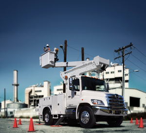
The newly revised A92.2 standard applies to the establishment of criteria for design, manufacture, testing, inspection, installation, maintenance, use, training and operation of vehicle-mounted aerial devices primarily used to position personnel installed on a chassis. The types of devices covered include extensible boom aerial devices, aerial ladders, articulating boom aerial devices, vertical towers or a combination of any of these.

An industry effort, the A92.2 subcommittee was a diverse group of between 30 and 36 individuals representing users and manufacturers. The subcommittee worked on the standard from 2001 until its eventual approval in July 2009.

For much of that time, the subcommittee was led by Gary McAlexander, president of Intercontinental Equipment Company. McAlexander, who joined the A92 revision effort in 1981, was chairman of the A92.2 subcommittee from 2001 until the 2009 revision was approved.

“The ongoing revision process for a standard like A92.2 is important because it ensures the safety of the utility crews that use aerial devices on a daily basis,” McAlexander said. “By reflecting the changes that have occurred in aerial design, work practices and regulations, we can help reduce incidents in real world operations.

“Communication is important in all endeavors,” McAlexander continued, “and in this case the exchange of information between manufacturers and users was especially valuable. This industry effort involving suppliers and utilities has helped ensure that a workable, effective and comprehensive standard is in effect.”

Joshua Chard, Ph.D., director – product & corporate safety at Altec Inc. now serves as chairman of the A92.2 subcommittee that completed its work on the newly revised standard. In June 2010, he covered the standard and its most recent changes at the 57th annual Electric Utility Fleet Managers Conference in Williamsburg, Virginia.

“The 2009 version of the standard contains many evolutionary changes,” Chard explained. “These changes contain the best language that could be agreed upon by the ANSI/ASC Subcommittee and Main Committee. In all cases they are meant to further the standard in its goal, “to prevent accidents associated with the use of Vehicle Mounted Elevating and Rotating Aerial Devices by establishing requirements for design manufacture, installation, maintenance, performance, use and training.”

Key Elements
The following represent some of the key elements of the newly revised ANSI A92.2 standard issued in 2009 that Chard covered in his presentation.

Although the requirements for general training carry over from the 2001 standard, a fourth bullet was added to the requirements for familiarization.

8.12.3 Familiarization – When an operator is directed to operate an aerial device they are not familiar with, the operator, prior to operating, shall be instructed regarding the following items:
1. The location of the manuals.
2. The purpose and function of all controls.
3. Safety devices and operating characteristics specific to the aerial device.
4. Under the direction of a qualified person, the trainee shall operate the aerial device for a sufficient period of time to demonstrate proficiency in the actual operation of the aerial device.

Additionally, the standard discusses the different types of qualified persons who typically operate aerial devices.

APPENDIX F – PRECAUTIONS FOR USE OF AERIAL DEVICES ON OR NEAR ENGERGIZED APPARATUS
Unqualified Person: A person who does not have approval to approach energized lines and apparatus and has received no significant training regarding the electrical hazards involved in the placing of an aerial device, platform occupants and their tools closer to energized lines and facilities than the distances listed.

Qualified Person: A person who has received training, understands and is conversant in the electrical hazards involved in the placing of an aerial device, platform occupants and their tools closer to energized lines and facilities than the distances listed, and has approval to perform the work.

Training of qualified person(s) is the responsibility of the employer or his designated contractor(s) and can be classroom, hands-on or a combination, as deemed appropriate by the employer for the degree of risk involved.

An unqualified person, as an operator, shall not approach energized conductors or facilities that will place the insulating or non-insulating aerial device, the operator and other platform occupants, and their tools, closer to such facilities that the distances shown.

A qualified communications person, as an operator, shall not approach energized conductors or facilities that will place the insulating or non-insulating aerial device, the operator and other platform occupants, and their tools, closer to such facilities than the distances set forth in Part 29 CFR 1910.268 and the National Electrical Safety Code.

A qualified line clearance tree trimmer, as an operator, shall not approach energized conductors or facilities that will place the insulating or non-insulating aerial device, the operator and other occupants, and their tools, closer to such facilities than the distances set forth in Parts 29 CFR 1910.268, 1910.269 or ANSI/ISA Z133.1.

A qualified lineman, as an operator, shall not approach energized conductors or facilities that will place the insulating or non-insulating aerial device, the operator and other platform occupants, and their tools, closer to such facilities than the distances set forth in Part 29 CFR 1910.269 and the National Electrical Safety Code. Higher levels of qualifications are required for electrical linemen to physically contact energized conductors and facilities from Category A, B and C aerial devices.

DEFINITIONS
The definitions section was expanded during the revision process. Of note was a clarification as to the role of the chassis insulating system:

Chassis Insulating System – An insulating system of dielectric components installed between the chassis and the upper insulating boom. 

5.2.5 The chassis insulating system may provide some protection for ground personnel should the portion of the aerial device between the upper insulating boom and the chassis insulating system inadvertently contact an energized conductor or apparatus such as a secondary circuit on a distribution system. When provided, the chassis insulating system does not have a voltage rating. Aerial devices with a chassis insulating system shall have means provided to bypass the chassis insulating system during electrical test, or bare-hand use.

Note: Insulating devices when used for bare-hand work (Category A) require shunting of an existing chassis insulating system.

Insulated Insulating Aerial Device – An aerial device with dielectric components designed and tested to meet the specific electrical insulating rating consistent with the manufacturer’s identification plate.

A significant change found in the design of insulated units is a requirement that lower controls be readily accessible in all boom positions and be installed such that an operator is not placed in the electrical path between the aerial device and the ground.

4.3.3 Lower Controls – Lower controls shall be readily accessible in all boom positions and shall provide a means to override the boom positioning upper controls provided the upper control system is intact.

The override mode shall maintain its function while unattended. The lower controls of insulating aerial devices shall be designed in such a manner that an operator is not placed in the electrical path between the aerial device and the ground

Two new requirements for operator aids are a slope indicator and an outrigger interlock device.

4.5.4 Slope Indicator – An indicator(s) shall be provided that is visible to the operator during setup to show whether the aerial device is positioned within limits permitted by the manufacturer. The allowable limits shall be shown on the unit and in the manual. For units designed for mobile operation such an indicator(s) shall be supplied in the cab.

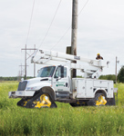
4.5.5 Outrigger Interlock Device – When an aerial device is equipped with outriggers, and their use is required to pass the stability tests of this standard, an interlock device shall be provided that prevents the boom from being operated from the stowed position until the outriggers have been deployed.

Deployment may be sensed when the outriggers meet resistance or by receipt of an indicative response that the outrigger deployment is beyond a predetermined position. The lifting of an outrigger during operation shall not disable boom functions. An interlock override switch may be provided; however, the override mode of operation shall disable automatically.

Note: The operation of outrigger interlocking devices does not assure aerial device stability. It serves only to remind the operator that the outriggers have or have not been deployed. See Section 10.10 (3). Changes were also made to the fall protection anchorage section.

4.9.4 Anchorage(s) for Personal Fall Protection
4.9.4.1 The manufacturer shall provide anchorage(s) on the boom, platform or platform mounting.

4.9.4.2 The location of the anchorage(s) shall be identified and the number of anchorages shall equal or exceed the number of permissible occupants. More than one occupant may attach to a single anchorage if the anchorage is rated and identified as being for more than one person.

4.9.4.3 Strength requirement. Anchorages shall be capable of withstanding a static force of 3,600 lbs. (16,000N) for each person allowed by the manufacturer on the attachment without reaching ultimate strength. The strength requirement shall apply only to the anchorage(s) and their attachments to the boom, platform or platform mounting.

Note: This does not imply that the aerial device is meant to meet or comply with this load requirement.

4.9.4.4 Connector requirement. Anchorage shall be compatible with a lanyard connector complying with ANSI/ASSE Z359.1-2007.

4.9.4.5 Surface. Anchorage(s) surfaces shall be free from sharp edges.

4.9.4.6 Pinch restriction. A lanyard connector shall not pinch between components having relative movement with the anchorage(s).

Note: See Sections 8.12.1, 9.3.1, 10.12.1 and 11.4.1 for more information pertaining to proper use of personal fall protection equipment.

The revision of the standard also made changes in the electrical sections. It clarifies the categories of insulated units with special attention given to the type of protection offered to the worker by the unit versus personal protective equipment.

5.1 Electrical Specifications – An aerial device with an insulated upper boom is commonly used to provide an additional layer of secondary protection from a path to ground through the boom and vehicle. This secondary protection is valuable; however, it cannot replace the worker’s primary protective equipment.

ANSI A92.2 CATEGORIES
Category A – Aerial devices which are designed and manufactured for work in which the boom is considered primary insulation (bare-hand work) shall have all conductive components at the platform end bonded together to accomplish equipotential of all such components. These aerial devices shall be equipped with a lower test electrode system. When these aerial devices are qualified for work above 138 kV, they shall be equipped with a gradient control device and conductive shield(s) over the lower test electrode system. For those aerial devices with ratings 138 kV and below, conductive shield(s) over the lower test electrode system are required. The necessity of a gradient control device is to be determined by the Qualification test.

Category B – Aerial devices which are equipped with a lower test electrode system, but are designed and manufactured for work in which the boom is not considered as primary insulation, but secondary, such as that using insulating (rubber) gloves. Category B aerial devices can be rated higher than 46 kV in order to facilitate changing them to Category A aerial devices for “bare-hand work.”

The manufacturer is reminded to consider in the design that “bare-hand work” requires the use of Category A aerial devices. Using Category B aerial devices on voltage levels above 46 kV requires the use of live line tools with appropriate dielectric ratings. These tools are to be depended upon for primary protection, just as in all cases where the boom is used as secondary protection (Categories B and C).

Category C – Aerial devices which are not equipped with a lower test electrode system and are designed and manufactured for work in which the boom is not considered as primary insulation, but secondary, such as that using insulating (rubber) gloves. These aerial devices are designed for voltages of 46 kV and below.

5.2.1 Insulating Systems – The insulating portions of the aerial device shall be identified in the manual and on the aerial device. All components crossing the insulating portions of the aerial device shall have electrical insulating values consistent with the design voltage rating of the boom, and when provided, of the chassis insulating system. The insulating system shall maintain the electrical insulating values in all working boom positions as defined by the manufacturer.

The above information is important to understand in light of the presence of metal components above the unit’s insulating sections.
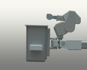
CONDUCTIVE BOOM TIP
Contact of any component at the boom-tip with an energized conductor can energize all components at the boom-tip, including the control handle.

This concept is important when maintaining minimum approach distances to boom tip components.

1910.269 (l)(2) Minimum Approach Distances – The employer shall ensure that no employee approaches or takes any conductive object closer to exposed energized parts than set forth in Table R-6 through Table R-10, unless:

(i) The employee is insulated from the energized part (insulating gloves or insulating gloves and sleeves worn in accordance with paragraph (l)(3) of this section are considered insulation of the employee only with regard to the energized part upon which work is being performed).

(ii) The energized part is insulated from the employee and from any other conductive object at a different potential.

(iii) The employee is insulated from any other exposed conductive object, as during live-line bare-hand work.

Note: Paragraphs (u)(5)(i) and (v)(5)(i) of this section contain requirements for the guarding and isolation of live parts. Parts of electric circuits that meet these two provisions are not considered as “exposed” unless a guard is removed or an employee enters the space intended to provide isolation from the live parts.

The revision of A92.2 for 2009 addresses this issue with allowances for control systems that incorporate High Electrical Resistance Components.

5.2.6 Upper Controls – The upper control conductive components are bonded together on Category A machines, but such bonding is optional on Category B and Category C machines. Categories B and C machines may incorporate control systems with high electrical resistance components. Machines that incorporate components for their electrical resistance shall receive an initial confirmation test and be subjected to the requirements for periodic inspections (See Sections 5.4.2.6, 5.4.3.6).

Controls that employ high electrical resistance components do not have a voltage rating and are not part of the insulating system that enables an aerial device to have an insulating rating. Whatever upper control arrangement is provided shall be identified. Specific warnings and advice shall be provided to the operator(s) that the upper controls do not provide protection in the event of electrical contact and are not a substitute for Minimum Approach Distances, cover-ups, rubber gloves and other personal protective equipment.

5.4.2.6 Confirmation test of upper control components with high electrical resistance. Upper controls that incorporate components for their electrical resistance shall be tested to assure resistance by testing them at 40 kV 60 Hz r.m.s. for 3 minutes with a maximum current level of 400 microamperes.

5.4.3.6 (Periodic) Confirmation Test of Upper Control Components with High Electrical Resistance. Upper controls that incorporate components for their electrical resistance should be tested to assure resistance by testing them at either 40 kV AC or 56 kV DC for 3 minutes with a maximum current level of 400 microamperes for the AC test and 56 microamperes for the DC test.

Covers and High Electrical Resistance upper controls offer new layers of protection for users of insulated aerial devices. This protection is valuable; however, it cannot replace the worker’s primary protective equipment.

Also dealing with this issue were changes to the requirements for manuals:

6.4 Manuals – The manufacturer shall provide a separate operators manual and a separate parts/ maintenance manual for each aerial device. Two sets of manuals shall accompany each device. The manuals shall contain:

(8) Facsimiles of all safety and operating decals and their location.

6.5.4 Instructional Markings. Markings shall be determined by the manufacturer or the manufacturer and user jointly to indicate hazards inherent in the operation of an aerial device. Instructional markings shall be provided for:

(9) Notice that fiberglass or plastic covers are not insulating.

(10) Notice that the aerial device shall not be operated with missing covers or guards, except as required for maintenance to the aerial device.

RESPONSIBILITIES OF DEALERS AND INSTALLERS
7.8 Training: The dealer or installer shall offer training or training materials that aid owners, users, operators, lessors and lessees in the operation, inspection, testing and maintenance of the aerial device. This training shall be offered initially and subsequently on request.

7.9 Maintenance Training: Dealer maintenance personnel shall be trained in inspection, testing and maintenance of the aerial device in accordance with the manufacturer’s recommendations.

7.8.1 Dealer or Installer as User: Whenever a dealer or installer directs personnel to operate an aerial device (inspecting, sales demonstrations or any form of use), the dealer or installer shall assume the responsibilities of users as specified in Section 9 of this standard. All personnel authorized to operate the aerial device shall have been trained in a program that meets the requirements of this standard.

Section 8 Responsibilities of Owners was reorganized and new items were added in the inspection and test requirements:

8.2.3 Frequent Inspection and Test – The following inspections and tests shall be performed by the operator immediately prior to first use at the beginning of each shift:
1. Conduct walk-around visual inspection looking for damaged components, cracks or corrosion, excessive wear and any loose, deformed or missing bolts, pins, fasteners, locking devices and covers.
2. Check all controls and associated mechanisms for proper operation to include, but not limited to, the following:
a. Proper operation of interlocks. 
b. Controls return to neutral when released and not sticking.
c. Control functions and operation clearly marked.
3. Check visual and audible safety devices for proper operation.
4. Visually inspect fiberglass and insulating components for visible damage and contamination.
5. Check for missing or illegible operational and instructional markings.
6. Check hydraulic and pneumatic systems for observable deterioration and excessive leakage.
7. Check electrical systems related to the aerial device for malfunction, signs of excessive deterioration, dirt and moisture accumulation.
8. Perform functional test to include, but not limited to, the following:
a. Set up aerial device for operation, including outriggers.
b. Cycle each aerial device boom function through its complete range of motion from the lower controls, except where operation through the complete range of motion would create a hazard.
c. Check functionality of emergency controls.

Any suspected items shall be carefully examined or tested and a determination made by a qualified person as to whether they constitute a safety hazard. All unsafe items shall be replaced or repaired before use.

8.2.4 Periodic Inspection or Test
(13) Condition and tightness of bolts and other fasteners in accordance with the manufacturer’s recommendation.
(17) If the aerial device has upper controls equipped with high electrical resistance components and the manufacturer so indicates, they should be electrically tested per 5.4.3.6.

Any suspected items shall be carefully examined or tested and a determination made by a qualified person as to whether they constitute a safety hazard. All unsafe items shall be replaced or repaired before use.

 8.2.5 Post Event Inspection or Test – After any reported event during which structural members of an aerial device or mobile unit are suspected of being subjected to loading or stresses in excess of design stress, such as after an accident involving overturning of the mobile unit or application of unintended external mechanical or electrical forces to the aerial device, the aerial device shall be removed from service and subjected to the applicable periodic inspection requirements in 8.2.4. In addition to the periodic inspection, supplemental non-destructive examination procedures or other tests to assist in detecting possible structural damage to the aerial device may be required. All damaged items shall be replaced or repaired before the unit is returned to service.

Also in Section 8 are some requirements for proper welding, use of aerial devices for intended applications, ownership notification and a prohibition on certain alterations.

8.4.2 Welding – Welding repairs of components or welds, designated as critical in the manufacturer’s manual shall be made in accordance with the manufacturer’s recommendations and shall meet the Structural Welding Code AWS D1.1-2006 and AWS D1.2-2003. Should the original manufacturer no longer exist, an equivalent entity may determine the required procedure.

8.5.1 Alterations – Altering or disabling the function of safety devices, guards or interlocks, if so equipped, shall be prohibited.

8.7 Transfer of Ownership – When a change in ownership of an aerial device occurs, it shall be the responsibility of the seller to provide the manufacturer’s manual(s) for that aerial device to the purchaser. It is the responsibility of the purchaser to notify the manufacturer of the unit model and serial number and the name and address of the new owner within 60 days. If the owner uses other entities as agents, e.g., brokers, for the sale or the arrangement of a sale of an aerial device(s) his responsibilities under this section continue.

9.4 Application – The employer and authorized operator(s) shall ensure that the aerial device is used only for intended applications as defined in the operating manual and that all recognized safety practices are observed.

Note: The user is directed to Appendix C for guidance as to appropriate applications.

9.5 Electrical Hazard – All applicable safety-related work practices intended to protect from electrical hazards shall be defined and explained to the operator by a qualified person. The operator shall maintain the appropriate Minimum Approach Distance (MAD) from energized conductors and apparatus, commensurate with the operator’s qualifications. See Appendix F for the information on the Minimum Approach Distances and other precautions.

The operators section was also reorganized to match the inspection requirements in Section 8.

RESPONSIBILITIES OF OPERATORS
10.7 Alterations – Altering or disabling the function of safety devices, guards or interlocks, if so equipped, is prohibited.

10.8 Observations – Observations during operation for any defects shall be conducted on an ongoing basis.

10.8.1 Pre-start Inspection
1. Conduct walk-around visual inspection, looking for damaged components, cracks or corrosion, excessive wear and any loose, deformed or missing bolts, pins, fasteners, locking devices or covers.
2. Check all controls and associated mechanisms for proper operation to include, but not limited to, the following:
a. Proper operation of interlocks.
b. Controls return to neutral when released and not sticking.
c. Control functions and operation clearly marked.
3. Check visual and audible safety devices for proper operation.
4. Visually inspect fiberglass and insulating components for visible damage and contamination. 
5. Check for missing or illegible operational and instructional markings.
6. Check hydraulic and pneumatic systems for observable deterioration and excessive leakage.
7. Check electrical systems related to the aerial device for malfunction, signs of excessive deterioration dirt and moisture accumulation.
8. Perform functional test to include, but not limited, to the following:
a. Set up aerial device for operation, including outriggers.
b. Cycle each aerial device boom function through its complete range of motion from the lower controls, except where operation through the complete range of motion would create a hazard.
c. Check functionality of emergency controls.

Any suspected items shall be carefully examined or tested and a determination made by a qualified person as to whether they constitute a safety hazard. All unsafe items shall be replaced or repaired before use.

10.9 Worksite – Before the aerial device is used, the worksite shall be surveyed for hazards such as:
1. Insufficient supporting surfaces such as soft ground or tamped earth fills.
2. Ditches.
3. Excessive slopes, drop-offs, curbs and floor obstructions.
4. Debris.
5. Overhead obstructions and electrical conductors.
6. Weather conditions.
7. Presence of unauthorized persons.
8. Road or worksite traffic.
9. Subsurface chambers such as underground utility components or septic systems.

The standard includes a new appendix, which discusses concepts important for work around energized conductors.

HANDLING ENERGIZED APPARATUS (APPENDIX F)
When the boom tip jib and/or winch of a category B or C aerial device is used for handling energized conductors and apparatus, the energized conductors and apparatus shall be insulated from the boom tip with electrical protection devices that are rated, tested and maintained for the appropriate rated line voltage. 

Boom tip jibs used in material handling on aerial devices shall be considered non-insulating unless the jib has been rated, tested and maintained for the appropriate line voltage.

Safety rules and work practices may vary significantly for different users, but one universal rule that applies is when jibs are used as a live-line tool with category B and C aerial devices, platform occupant(s) must use protective equipment such as gloves and cover-ups. 

If the winch line is used to lift energized apparatus, the energized apparatus shall be insulated from the jib tip with electrical protection devices that are rated, tested and maintained for the appropriate line voltage. 

The winch line shall not be considered as insulating. For multi-phase lifting with conductor holders and a cross-arm, phase to phase protection shall be accomplished with a cross-arm that is rated, tested and maintained for the appropriate line voltage.

Insulating Liners and Insulating Baskets – A dielectrically tested insulating liner or insulating basket is intended to prevent electrical current flow through the lower extremities of the basket occupant. This is one element in a system approach that includes both work practices and materials designed to avoid electrical contact. Such a liner or basket shall not be considered primary insulation.

Minimum approach distances must be maintained by the electrical worker to assure clearances between objects at different electrical potential when performing live-line work. It applies to the worker’s reach including any non-insulating object above the insulated section of the aerial device. The Minimum Approach Distances may be obtained from sources such as, but not limited to:
ANSI C-2 National Electrical Safety Code
ANSI C-1 National Electrical Code
CFR 29 1926.950
CFR 29 1910.269
Work practices
(j) Live-line tools.
(1) Design of tools. Live-line tool rods, tubes and poles shall be designed and constructed to withstand the following minimum tests: (i) 100,000 volts per foot (3281 volts per centimeter) of length for 5 minutes if the tool is made of fiberglass-reinforced plastic (FRP).
(2) Condition of tools.
(i) Each live-line tool shall be wiped clean and visually inspected for defects before use each day.
(ii) If any defect or contamination that could adversely affect the insulating qualities or mechanical integrity of the live-line tool is present after wiping, the tool shall be removed from service and examined and tested according to paragraph (j)(2)(iii) of this section before being returned to service.
(iii) Live-line tools used for primary employee protection shall be removed from service every two years and whenever required under paragraph (j)(2)(ii) of this section for examination, cleaning, repair and testing.

Editor’s Note: The annual Electric Utility Fleet Managers Conference (EUFMC) hosts representatives of more than 50 companies in the U.S. and Canada, including investor-owned electric utilities, electric cooperatives and electrical contractors, and more than 270 representatives from more than 95 manufacturers and service providers. The conference includes an Equipment Demonstration and Display, which in 2010 was the site of more than 60 exhibits. EUFMC will be held June 19-22, 2011 at the Williamsburg Lodge and Conference Center in Williamsburg, Va. For more information, visit www.eufmc.com.